With my front end back together and bolted onto the frame, it’s on to the rear wheel. Since I’m using an aftermarket hardtail Sportster frame from Paughco, there were quite a few parts that needed to be made in order to get the rear wheel mounted and lined up correctly. Of course, the first step was to bolt the engine back into the frame, so there was something I could align the rear wheel to…
Paughco provides all the same mounting locations as a stock Harley frame, so bolting in the motor was a fairly straight forward job. Just like with the stock frame, you start by attaching the rear lower motor mounts and then work your way around the engine to the front lower motor mounts, the front upper motor mounts and finally the top motor mount.
I’ll have to fab a custom top motor mount, so I left that one for later. While all the bolts lined up easily, it turns out that Paughco uses different thickness mounts, so I had to swap out most of the 3/8”-24 bolts for slightly different sizes.
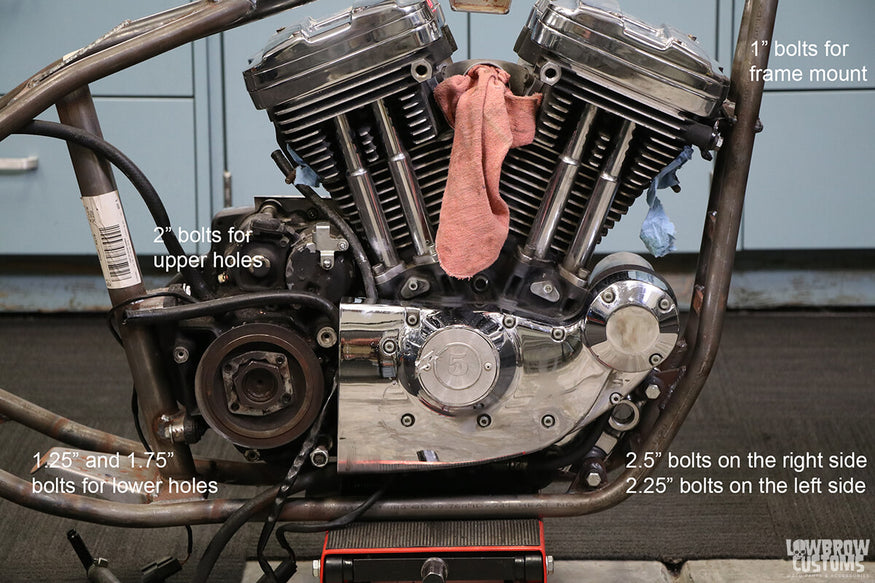 Different length bolts are needed for mounting the engine in an aftermarket frame.
After getting the engine mounted firmly in place, I moved on to upgrading my final drive from a belt to a chain. I picked up a Sportster belt to chain conversion kit from Lowbrow Customs and you can check out the Sportster chain conversion kit how-to instructions here.
One thing I’ll add is that if you can beg, borrow or buy a 1-7/8” impact socket and an impact wrench, the job is so much easier. In the process I also found out that all the internal teeth on my front pulley were just about worn out, so the timing of this couldn’t have been better.
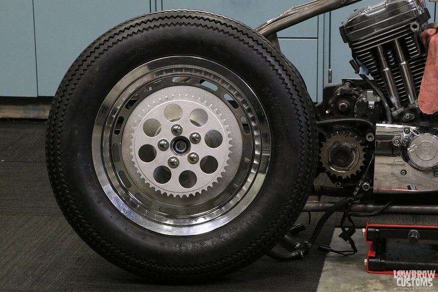 Make sure to use blue thread locker on every bolt of both sprockets.
I tried test fitting the rear wheel with my stock Sportster axle and discovered that the axle was a little too long and that the slots in the axle plate were a little too wide. In order to take up the extra length and width, I fabricated a set of axle adjusters out of 1.3125” diameter stainless steel bar.
I made them wide enough to take up the extra length of the axle and turned down a shoulder on each one that would insert into the axle plate to take up the extra width.
On the left-hand side, the threaded portion of the axle was partially inside the new adjuster, so I cut a stepped hole in that adjuster to provide some extra support for the narrower threaded section of the axle. I also fabricated a pair of 3” screws and jam nuts to complete the set up.
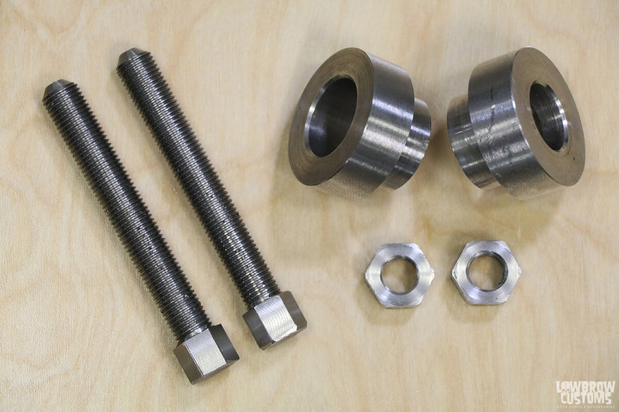 Stainless steel axle adjusters won’t require additional plating to stay rust free.
The axle adjusters allowed me to finally mount the rear wheel in the frame and start on the tedious process of getting it aligned correctly. The first step was to get the tire centered with the frame.
Most people use a loop of string with a rubber band in the middle to help do this, but I never felt like I was getting a precise enough measurement with this method. Instead, I decided to assume that a reputable frame company like Paughco would weld all their frame mounts in a jig and that the fuel tank mount and seat mount would be centered on the frame.
I then had a straight edge cut out of ¼” plywood using a laser cutter with cut outs for the fuel tank mount and seat mount and a center line marked at the end. The resulting piece of wood fit on top of the frame, ending right at the rear tire, making aligning the rear wheel a breeze.
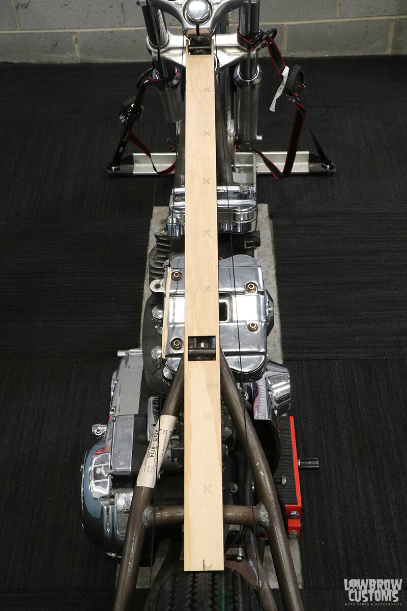 Laser cut wooden straight edge for centering the rear tire.
Now it was onto squaring the rear sprocket with the front sprocket. I clamped a piece of c-channel to the top of the rear sprocket using two clamps to ensure that it was straight. Then I moved the rear wheel until the straight edge lined up perfectly with the front sprocket.
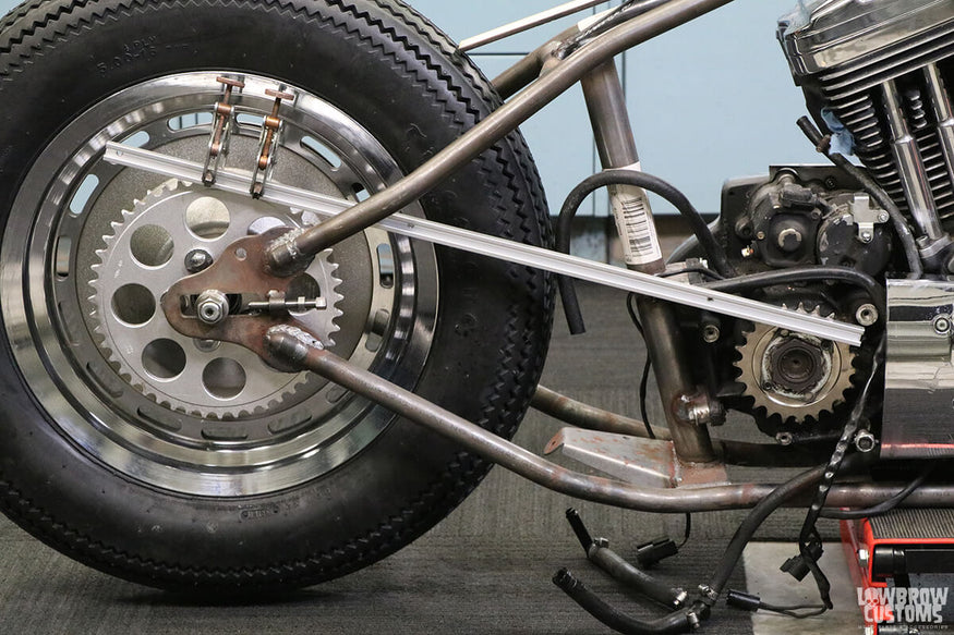 Make sure to clamp the straight edge on the teeth and not the wider center of the rear sprocket.
During the alignment process, I discovered that the rear wheel needed to move over about 0.2” to be perfectly centered. The easiest way to do this was to mill a spacer to fit between the rear sprocket and the rear hub out of a piece of 0.2” thick aluminum plate.
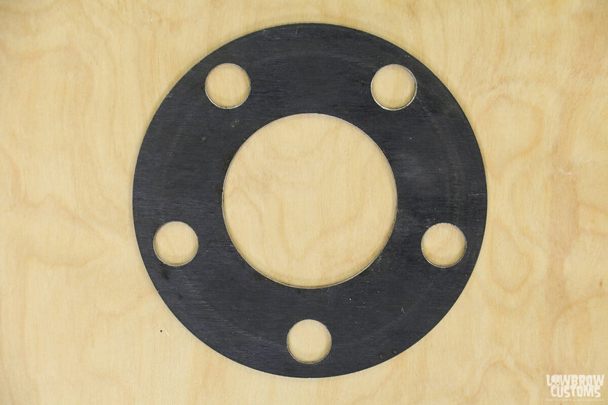 Aluminum spacer used to move the tire over 0.2".
Once the spacer was installed between the rear sprocket and the rear hub, I was finally satisfied with the position of the rear wheel. At this point I needed to make some new wheel spacers for each side.
Technically I could have reused the spacer in between the rear hub and the rear brake bracket, but I decided to remake it as well so that all the spacers would match. In order to precisely measure the sizes needed for the wheel spacers, I used a telescoping gauge.
If you’ve never seen one, it is basically a T-shaped tool with lockable spring-loaded heads. You compress the heads in between the two surfaces you wish to measure and then lock them in place. Once the tool is removed, you then measure it with a pair of calipers to find the distance.
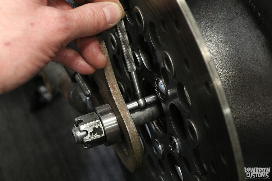 Using a telescoping gauge is an easy and accurate way to measure wheel spacers.
Using the same 1.3125” diameter stainless steel rod, I made the two wheel spacers for the left-hand side of the axle. For the right-hand side, I started out with a piece of 2” diameter stainless steel rod and turned it down to 1.3125” leaving a wider section to fill in the 2” hole in the center of the rear sprocket.
Since the sprocket spins and the wheel spacer does not, I made the wider section 1.875” to allow for clearance and water drainage.
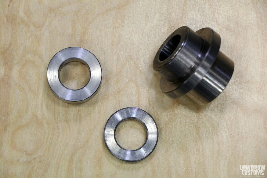 More rust-free stainless steel for the wheel spacers.
To finish the job, all that was left was to slide on the axle spacers and tighten up the axle nut.
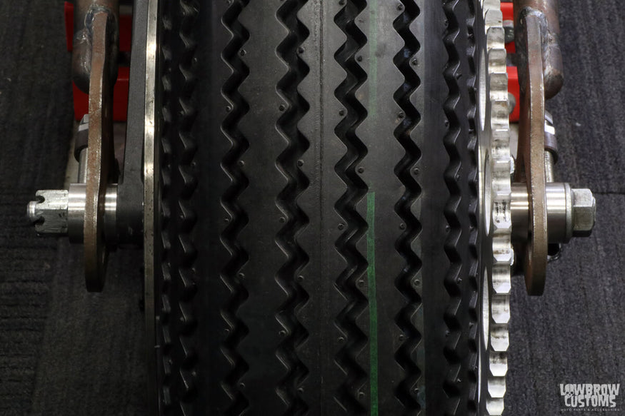 No one will appreciate the hours taken to properly align a rear wheel…
In my next installment, I’ll show how some camera tricks and a couple of computer programs can be used to help modify a stock rear brake bracket into something that looks as good as from the factory.
Words and photos by: Panhead Jim

Enjoying this article? Check out the first three articles in this series here:
Panhead Jim Builds a Sportster Chopper - Part 1
Related Products


