When I started on this build, I decided to go with an aftermarket hardtail frame instead of doing a weld-on Sportster hardtail frame because I wanted to retain my OEM Sportster frame. Then 50 years from now I could restore my ’96 Sportster back to original and sell it for millions of dollars. While that may be a bit farfetched, I thought it would save time going with a pre-built frame because everything would just bolt right up. Well, that dream lasted until I got to the front end and found out that all the time I saved skipping the weld-on hardtail would be used grafting the stock front end to my aftermarket frame.
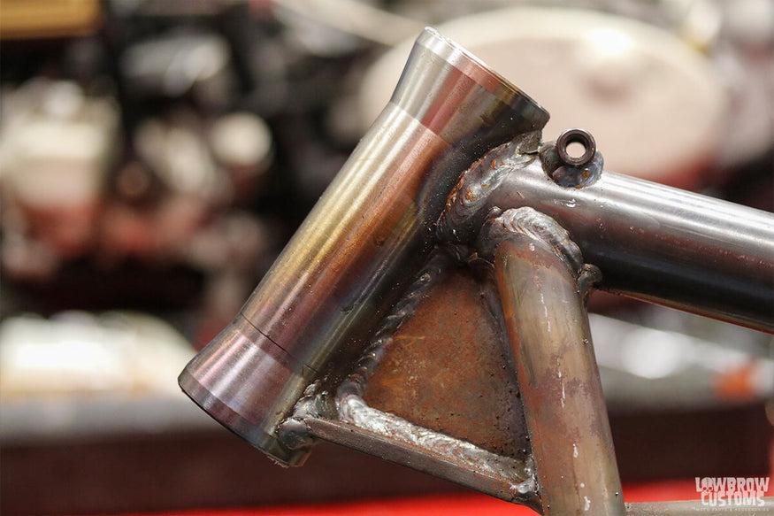
Standard aftermarket frame neck, without castings for bearings or fork stops.
The heart of the problem was the frame neck. The stock Harley neck allows for the bearings to fit right in the casting whereas the aftermarket frame needed neck cups added to house the bearings. Harley used this same arrangement for years and getting neck cups is no big deal. Of course, they did require being turned down a few thousandths to fit into the neck, but that is no surprise when assembling parts from different manufacturers…
Now the real issue arose when I started trying to figure out the fork stops. The stock frame neck has a nice rectangular piece welded right on the front which works with two castings on the lower triple tree to provide a means for keeping the front end from turning too far in either direction. Since I am using neck cups on my aftermarket frame, this set up obviously no longer functions. Luckily, you can buy neck cups with a built-in internal fork stop which solves all your problems and looks clean to boot.
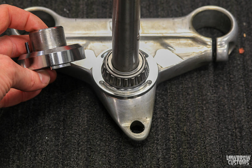 The "front tooth" on the neck cup fits into the slot on the plate under the bearing creating an internal fork stop.
The internal fork lock has a pretty simple design. You have a slotted plate which mounts onto the lower triple tree right under the bearing and your lower neck cup has a “front tooth” that rides in the slot when everything is assembled. The slot allows the front end to turn 45 degrees in each direction. For this to work, both the slotted plate and the neck cup need to be fixed in place. This is achieved with 8 metal dowel pins which are mounted into the lower triple tree and the neck.
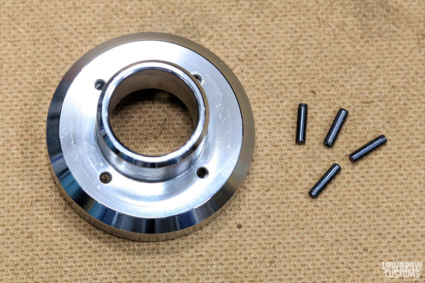 Metal dowel pins inserted through the neck cup and into the frame neck keep the neck cup from rotating.
To make things more challenging, the neck cup kit came with no directions or mechanical drawings. Before starting, referencing a Harley fork size chart can simplify the process by ensuring compatibility and proper measurements for your build. The lower triple tree was fairly easy to bore as it could just be clamped up in a vice on a milling machine. After boring the holes I also milled off the old fork stops to clean things up a bit.
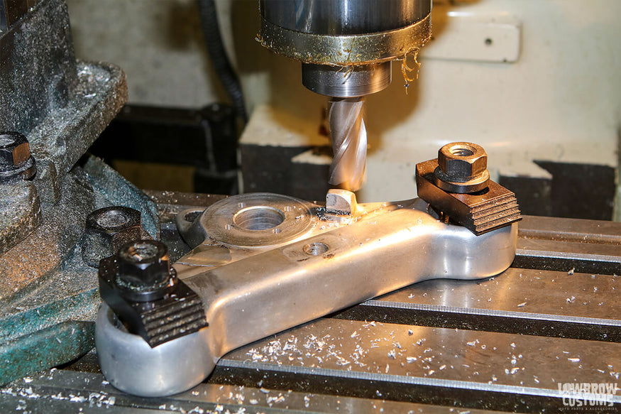 The external fork stops were removed after boring the holes for the internal fork stop plate.
The frame neck had to be drilled by hand, which required first making a drill guide and then making an alignment tool so that the holes could be bored perfectly in line with the frame. Drilling the holes out of alignment would me that the front end would turn further in one direction than the other. The depth of the holes was also critical, so I set the bit length in the drill chuck with a set of calipers. For both sets of holes, I used an end mill instead of a drill bit so that the bottom of the holes would be flat.
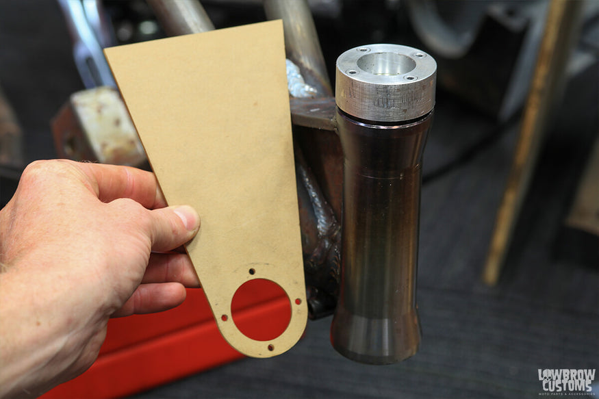 A template was used to square the drill guide with the front down tubes.
Once all the machining / drilling was completed I pressed in all the bearing races and bearings before assembling the triple trees. Then it was on to the lowers.
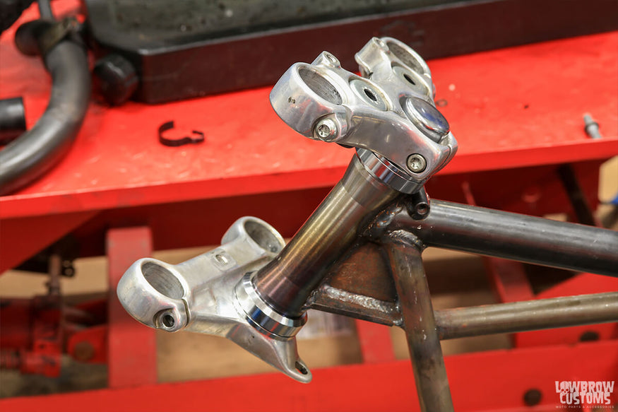 Triple trees assembled and ready for forks.
After fulling disassembling the forks, I took the lowers and turned them down on the lathe to remove the front fender brackets. For now, I decided to keep the front brake, just because stopping seems like a useful option.
Turning down lowers is just a three-step process. First, I cut off the bulk of the fender mounts with a band saw, then I finished removing remainder of the mounts on the lathe and finally smoothed everything out with sandpaper. The one real trick is you must have what is called a “live center” on the tailstock of your lathe so that the legs will be supported on each end and spin smoothly.
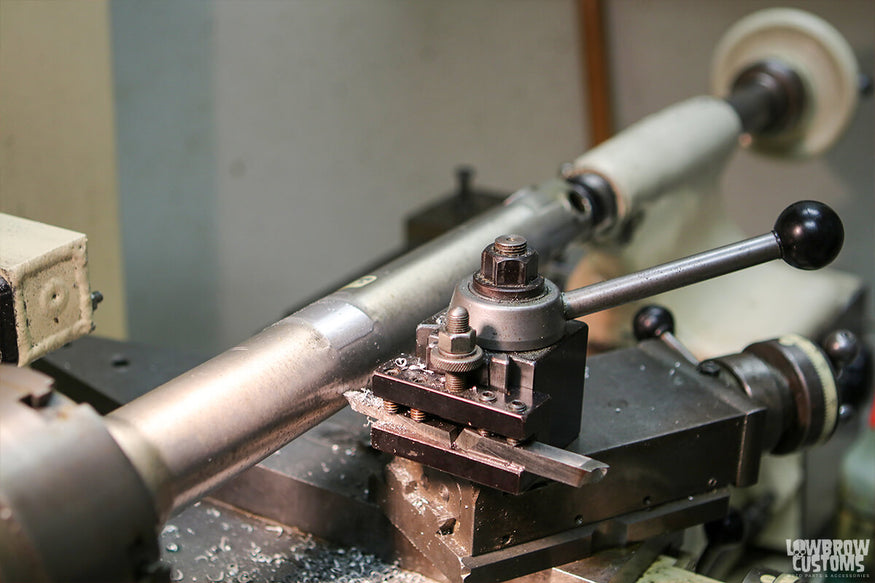 Turning down the fork lowers on a lathe to remove the front fender mounts.
With the legs shaved, it was on to reassembly and having my factory service manual made this go fairly smoothly. Since my aftermarket frame has 5 degrees more rake than my original frame, I went ahead and ordered a set of 6” over tubes to level the bike back up. I also picked up a rebuild kit as my original seals were pretty well worn out after being on the bike for almost 25 years.
To help speed along the reassembly, I made two tools for installing seals and bushings. Both were essentially precision cut pieces of pipe that could slide over the fork tubes and hammer down on the fork lowers. I made one from aluminum for knocking in metal parts and one from Delrin for knocking in rubbers seals and the chrome dust caps. I’m pretty sure that a piece of PVC pipe can also be used too if you don’t want to spend an hour turning solid rod into pipe on a lathe.
 Precision cut "pipe" used to drive in fork seals.
Once both front forks were assembled, I slid them into the triple trees and clamped them down. I used a straight edge to make sure that the top of each fork protruded the same amount through the upper triple tree. Since these will be taken apart and sent out to be polished before final assembly, I skipped adding fork oil and went straight to bolting on the front wheel.
 Use a straight edge to help line up the tops of the forks in the triple trees.
Now I am halfway to a rolling chassis and ready to take on the challenges of getting the rear wheel installed correctly. Next, I’ll be converting to chain drive, modifying the stock brake mount, turning out some custom spacers and cutting down my stock axle. Should be fun…
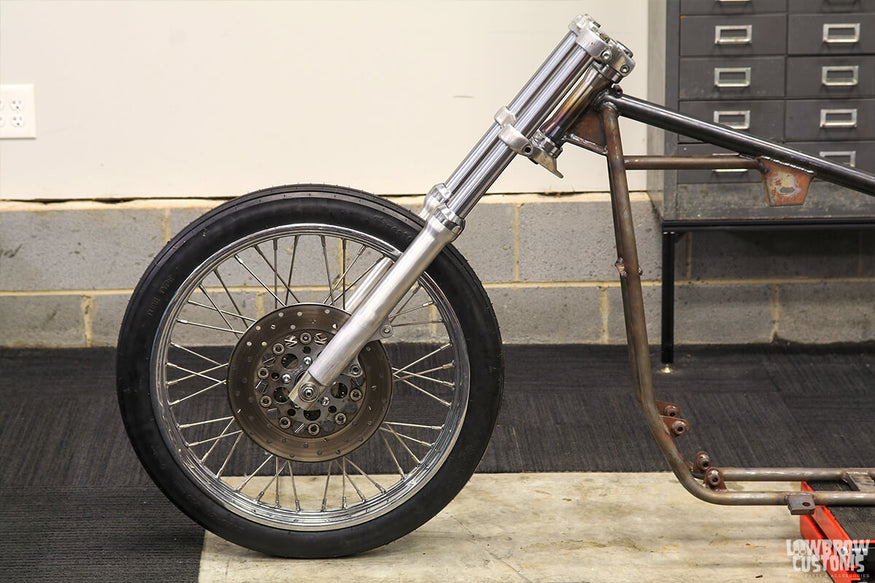 Front end mockup complete.

Enjoying this article? Check out the first two articles in this series here:
Related Products


